bootstrapping
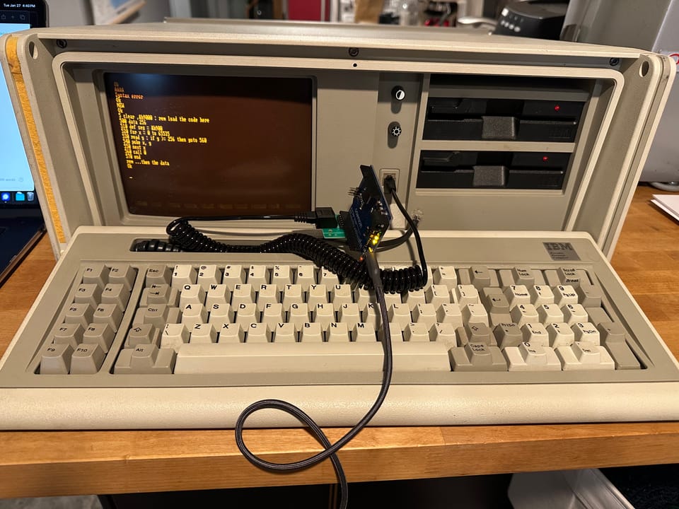
I spent a bunch of time hacking on my IBM 5155 Portable Personal Computer in preparation for my recent talk at DistrictCon about "neithers" – behaviors that are neither bug nor feature. One of my favorite such "neither" behaviors is the boot-time keyboard reset logic in early IBM PC BIOS.
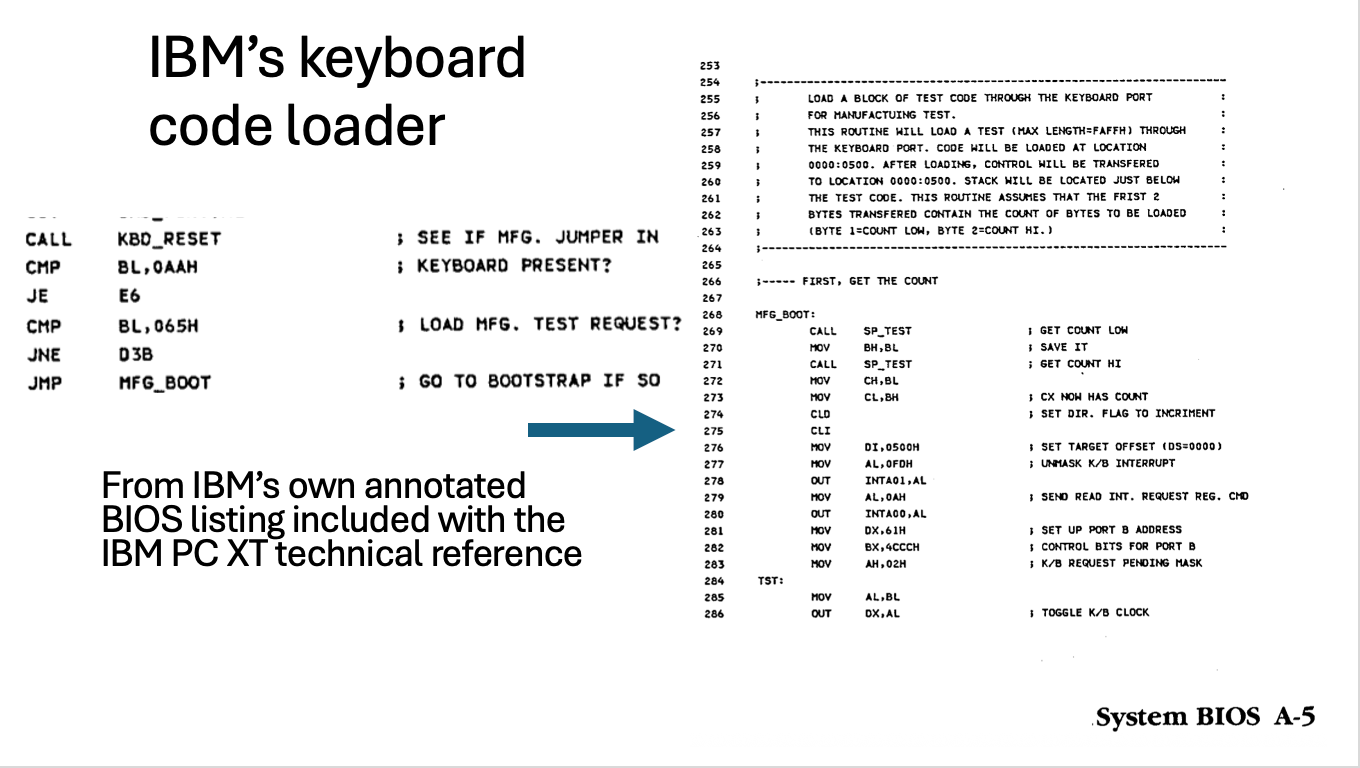
In the PC keyboard protocol (in certain machines built from 1981 to 1987), keyboards return the byte 0xAA after reset to indicate that they have successfully completed their own self-test. The BIOS checks for one other value, 0x65, that indicates the thing plugged into the keyboard isn't a keyboard at all but a code loader used at the factory for extended testing. In this case, the PC loads code directly from the keyboard port and jumps to it. That seems kind of interesting.
It's doubly interesting for me, because my PC has only floppy drives and I have no formatted 5.25" diskettes, let alone any with an operating system for this PC. So what to do?
Well, I could boot it from the keyboard port in that way and upload a program to format a diskette and transfer a DOS image to it also over the keyboard port. This would work, but the development environment is kind of hostile. The PC actually has a pleasant and interactive development environment built into ROM – IBM's Cassette BASIC.
People have been bootstrapping machines since there were machines, and the IBM PC family in particular for more than 40 years. The surfaces available on the IBM side remain essentially the same: a cassette port on the PC and PCjr, possibly a printer, serial, or other IO port on an expansion card. Certainly the keyboard. What changes over time is the likelihood that the prerequisite pieces are in a given hacker's junk box. If what you had was a serial port on another system, a serial bootstrap was easy enough to type in (with the caveat that Cassette BASIC had no serial support itself, so you had to assemble this as well).
These days, I'm more likely to have an Arduino or a Pi Pico in my bag than I am to have a dedicated USB-to-serial interface. In that case, the keyboard port alone is sufficient and requires nothing but three wires from the PC to (5V tolerant) general-purpose I/O pins on the microcontroller. Ground, data, and clock.
// PC, PC XT keyboard protocol as serial-to-keyboard bridge,
// ascii to scancodes

// any pins are fine
unsigned char xt_clock = 3, xt_data = 2,
unsigned char xt_pwr = 5, xt_gnd = 4;
unsigned char init_byte = 0xAA; // keyboard BAT OK

int ishi(int p) { return digitalRead(p); }
int islo(int p) { return !digitalRead(p); }
void release(int p) { pinMode(p, INPUT); digitalWrite(p, HIGH); }
void assert(int p) { digitalWrite(p, LOW); pinMode(p, OUTPUT); }
void assert_usecs(int p, int usecs) {
  assert(p); delayMicroseconds(usecs); release(p);
}

unsigned char asc_to_sc[128];
unsigned char asc_to_meta[128];
// map an ascii character (and optional shifted version)
// to a keyboard scancode
#define MCSC(c, s, sc) (asc_to_sc[c] = asc_to_sc[s] = sc, asc_to_meta[s] = 0x2A)
// the same, but also a ctrl-char variant
#define MCSCC(c, s, _cc, sc) (asc_to_sc[c] = asc_to_sc[s] = sc, asc_to_meta[s] = 0x2A, asc_to_meta[_cc] = 0x1D)

#define HOST_POWER_OFF 1
#define DO_BAT 2
#define IDLE 3
#define BAT_WAIT 4
#define DO_BAT_ACQUIRE_CLOCK 8

unsigned char state = IDLE;

void setup() {

  // ghetto gnd
  if(xt_gnd) {
    pinMode(xt_gnd, OUTPUT);
    digitalWrite(xt_gnd, LOW);
  }
  // arduino can be parasitically powered this way but
  // we also need it as a sense
  pinMode(xt_pwr, INPUT);
  pinMode(xt_clock, INPUT); release(xt_clock);
  pinMode(xt_data, INPUT); release(xt_data);

  memset(asc_to_sc,0,sizeof(asc_to_sc));
  memset(asc_to_meta,0,sizeof(asc_to_sc));

  // first row
  asc_to_sc[0x1b] = 0x01; // escape
  MCSC('1', '!', 0x02); MCSC('2', '@', 0x03);
  MCSC('3', '#', 0x04); MCSC('4', '$', 0x05);
  MCSC('5', '%', 0x06); MCSC('6', '^', 0x07);
  MCSC('7', '&', 0x08); MCSC('8', '*', 0x09);
  MCSC('9', '(', 0x0a); MCSC('0', ')', 0x0b);
  MCSC('-', '_', 0x0c); MCSC('=', '+', 0x0d);
  MCSC(0x08, 0x00, 0x0e); // backspace

  // second row
  MCSC(0x09, 0x00, 0x0f); // tab
  MCSC('q', 'Q', 0x10); MCSC('w', 'W', 0x11);
  MCSC('e', 'E', 0x12); MCSC('r', 'R', 0x13);
  MCSC('t', 'T', 0x14); MCSC('y', 'Y', 0x15);
  MCSC('u', 'U', 0x16); MCSC('i', 'I', 0x17);
  MCSC('o', 'O', 0x18); MCSC('p', 'P', 0x19);
  MCSC('[', '{', 0x1a); MCSC(']', '}', 0x1b);
  MCSC('\n', 0x00, 0x1c); // enter

  // 1d == caps lock
  MCSC('a', 'A', 0x1e); MCSC('s', 'S', 0x1f);
  MCSC('d', 'D', 0x20); MCSC('f', 'F', 0x21);
  MCSC('g', 'G', 0x22); MCSC('h', 'H', 0x23);
  MCSC('j', 'J', 0x24); MCSC('k', 'K', 0x25);
  MCSC('l', 'L', 0x26); MCSC(';', ':', 0x27);
  MCSC('\'', '"', 0x28); MCSC('`', '~', 0x29);

  // 2a shift. 2b?
  MCSC('\\', '|', 0x2b);
  MCSC('z', 'Z', 0x2c); MCSC('x', 'X', 0x2d);
  MCSC('c', 'C', 0x2e); MCSC('v', 'V', 0x2f);
  MCSC('b', 'B', 0x30); MCSC('n', 'N', 0x31);
  MCSC('m', 'M', 0x32); MCSC(',', '<', 0x33);
  MCSC('.', '>', 0x34); MCSC('/', '?', 0x35);

  MCSC(' ', 0x00, 0x39);

  // convert break (from ctrl-c) to ctrl-scroll lock
  asc_to_sc[0x03] = 0x46; // scroll lock
  asc_to_meta[0x03] = 0x1d; // ctrl

  Serial.begin(9600);
}

int
write_byte(unsigned char val) {
  while(!ishi(xt_clock)) if(!ishi(xt_pwr)) {
    state = HOST_POWER_OFF; return -1;
  }

  assert_usecs(xt_clock, 100); // RTS
  while(!ishi(xt_data)) if(!ishi(xt_pwr)) {
    state = HOST_POWER_OFF; return -1;
  } // this is the CTS;

  unsigned char i;
  for(i = 0 ; i < 8 ; i++) {
    delayMicroseconds(25);
    (val & (1 << i)) ? release(xt_data) : assert(xt_data);
    delayMicroseconds(25);
    assert_usecs(xt_clock, 50); // host samples on this edge
  }

  release(xt_data);
  return 0;
}

unsigned int counter = 0, trigger = 0;
unsigned char inter_char_delay = 7; // ms
unsigned char s = 0, m = 0, rx_byte = 0 ; // Serial.read();

void loop() {
  if(islo(xt_pwr)) { state = HOST_POWER_OFF; }

  switch(state) {
  case HOST_POWER_OFF:
    // wait for host to power on
    if(ishi(xt_pwr)) { trigger = counter ; state = BAT_WAIT; }
    break;
  case DO_BAT_ACQUIRE_CLOCK:
    // wait for host to release clock
    if(ishi(xt_clock)) state=DO_BAT;
    break;
  case DO_BAT:
    write_byte(init_byte); delay(1); state = IDLE;
    break;
  case IDLE:
    if(islo(xt_clock)) { trigger = counter; state = BAT_WAIT; break; }

    if(Serial.available()) {
      rx_byte = Serial.read(); if(rx_byte & 0x80) break;

      s = asc_to_sc[rx_byte & 0x7f];
      m = asc_to_meta[rx_byte & 0x7f];
      // meta make, scancode make/break, meta break
      if(m) { write_byte(m); delay(inter_char_delay); }
      if(s) {
        write_byte(s); delay(inter_char_delay);
        write_byte(0x80 | s); delay(inter_char_delay);
      }
      if(m) { write_byte(0x80 | m); delay(inter_char_delay); }
      delay(60); // keyboard flow control is art, not science
    }
    delay(1);
    break;
  case BAT_WAIT:
    if(islo(xt_clock)) {
      if((counter - trigger) > 10) state = DO_BAT_ACQUIRE_CLOCK;
      delay(1);
    } else state = IDLE; // clock went back hi before timeout
    break;
  }
  counter++;
}
Anyhow, there's an Arduino sketch to get you started with your own bootstrapping. I guarantee neither that it's reliable, nor secure, nor useful, nor final. I guarantee only that it's under two hundred lines and that I like it.
It's not hard to extend this into the manufacturing mode, but that mode is possibly less useful for bootstrapping since the machine isn't fully initialized at that point.
With that, here's the script I use most frequently to convert binary data to BASIC data statements for use with a stub loader:
#!/usr/bin/env node

fs = require('fs');
filename = process.argv[2];
width = 16
base = 18
b = fs.readFileSync(filename);
s = "" + base + " data ";
for(let x = 0 ; x < b.length ; x++) {
  if(x % width) s += ","
  s += "" + b[x].toString(10);
  if(!((x + 1) % width)) {
    console.log(s); base++; s = "" + base + " data "
  }
}
console.log(s);
Member discussion