DB25 #10 -- double A
You know what's worse than a hipster clacking away on a loud mechanical keyboard in your favorite cafe?
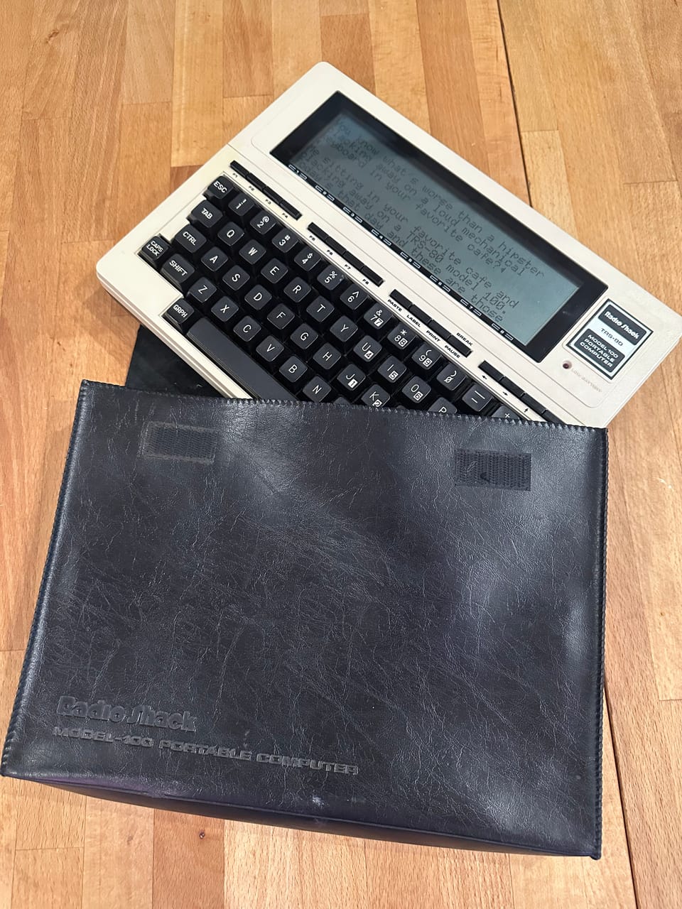
Me sitting in your favorite cafe and clacking away on a TRS-80 model 100. Today's that day and these are those clacks.
The Model 100 is on of the most frequent guest stars on Paper Tiger – we featured the upgraded Model 102 with 24k as part of the 24 x 24k for 2024 lineup. My own machine is an older 100 loaded with the full complement of 32k RAM and my machine is back in the studio today to show off its DB-25 serial port. Maybe fairer to say that it is the studio today.
Despite the 25 pins for serial connectivity on the back of my machine, only 8 are electrically connected:
1: ground (not listed on many online pinouts)
2: tx
3: rx
4: RTS
5: CTS
6: DSR
7: ground
20: DTR
A complete schematic is available here.
Why would the first serious laptop computer waste space for an over-large connector? There is a smaller DE-9 for a barcode scanning wand, a DIN connector each for the modem and cassette tape interface, all basically serial ports. In 1983, the PC industry was about to shift from the DB-25 connector for serial to more compact forms. The Apple ][ and Apple Lisa both used the DB-25, but the compact Macintosh introduced in 1984 switched to the DE-9. IBM switched to the DE-9 on their PC machines with the introduction of the PS/2 in 1987.
The simple reason that the 100 used the larger connector is that was the cable end you were most likely to be offered. You could take the 100 to a remote lab or office and use the equipment and cables already there.
Maybe a better question is why the serial port had ever used such a large connector. For that, we need to go back to 1960 and Recommended Standard 232. Who was doing this recommending, anyway? In 1960, it was the Electronic Industries Association, the trade group and patent pool that grew out of Chicago's Associated Radio Manufacturers syndicate started in the 1920s. Industry-backed standards have a more improvisational "yes, and" spirit than monopoly standards. RS-232 is no exception. The standard wasn't intended to connect one computer directly to another. As a practical matter, who had two computers in one place in 1960 anyhow? RS-232 was designed to connect a data terminal (DTE) like a teletype, to a piece of data communications equipment (DCE) like a modem and the standard was informed by manufacturers of both types of equipment.
The serial part, just one damn thing after another, is the least complicated part. Transmit data on pin 2, receive data on pin 3, referenced to a signal ground on pin 7. Flip those pins around on one end if connecting two computers back to back. On pin 1, we have a protective ground. This gets connected only on one side. On pin 4, we have request to send (RTS) used by the terminal end to tell the modem end that it should send data. For back to back (called null modem), the complement of this signal is on pin 5, clear to send (CTS) which the modem uses to indicate that it is ready to receive data. On pin 6, we have data set ready (DSR) used by the modem to indicate that it is present and ready. For back-to-back, this is the complement of data terminal ready (DTR) on pin 20. Except that DTR is also sort of the complement of carrier detect (CD) on pin 8.
Most hackers have never used a signal beyond those. Pins 9 and 10 were reserved for data set testing. Pin 11 was unassigned. Pins 12, 13, 14, 16, 19 were secondary CD, CTS, tx, rx, RTS for an optional second channel on the same cable. Pin 15 was the transmit clock! That's right, RS-232 had both synchronous and asynchronous modes. Pin 17 was the receive clock. Pin 18 was used by the terminal to place the modem in local loopback mode that fed the modulator output back into the demodulator input. Pin 21 was a remote loopback. Here, the terminal requests that the modem request of a modem on the far end that it loop data through its demodulator and modulator to check the link. Pin 22 is a ring indicator (RI), asserted by the modem when a ring signal is present on the telephone line. Pin 23 is the one-lane bridge of RS-232 signals. Either the terminal or the modem but not both may assert this signal to indicate which of two pre-arranged baud rates should be used on the circuit.
Pin 24 was an external transmitter clock (ETC). A terminal with a stable time base could share this with a terminal when in asynchronous mode.
Where did all these Jurassic signals go in the "modern" DE-9 serial cable? Well, the circuit called the "Universal Asynchronous Receiver/Transmitter" (UART) went from an entire line card to a single chip in 1970. Most microcomputers had only one UART, so the second channel pins were superfluous. A shrink from card to chip also made the UART reliable, or at least difficult to test, so some of the diagnostic features on the cable fell away. The value of synchronous modes faded as UART chips demonstrated their ability to stay synchronized at high data rates. As data rates climbed higher, the marginal overhead of protocol framing with stop, start, and parity bits seemed more than worthwhile.
The rest of the signals were killed by the microcontroller. The original Hayes 300-baud smart modem used a Zilog microcontroller to implement as "AT" commands all of the missing serial port functions and so many more that we still use these commands today.
The built-in modem in the Model 100 may have been one of the last popular modems not to use AT commands. The microcontroller in the Hayes modem was speedier than the 8085 clone used as the main processor in the Model 100!
The simple modem in the Model 100 has a physical switch on the side to indicate whether its modem is the one placing a call, or receiving. No ATA or ATDT here.
The Model 100 may be one of the first practical devices with a DB-25 port that was powered by AA batteries. Tell me if you know of another.
Member discussion